Choosing the right Cnc Coupling in 2026 requires more than matching shaft diameters. The correct part must support accuracy, speed, torque, and long service life. A milling spindle may face rapid acceleration, vibration, and heat during one production cycle. A rotary axis may need low backlash for clean contours and repeatable positioning. These conditions demand different coupling characteristics.
A reliable selection process begins with verified machine data. Check the motor torque, peak load, shaft bores, operating speed, and available installation space. Review the actual misalignment, not only the values shown on a drawing. Flexible couplings can absorb angular, parallel, and axial movement, but every design has limits. Excessive flexibility may reduce positioning stability. Excessive stiffness may transfer damaging loads to bearings.
Material choice also matters. Aluminum offers low inertia, while steel may provide greater torsional strength. Clamp hubs can simplify maintenance, but poor tightening can cause slippage. Keyways, set screws, and clamping systems each affect service reliability. Small details matter.
There is no universal best coupling.
Experienced engineers compare manufacturer specifications with real operating conditions. They also inspect failure evidence, such as fretting marks, cracked elastomers, loose hubs, or unusual noise. A catalog rating alone cannot predict every result. Temperature, contamination, installation quality, and maintenance habits may change performance. Some selection decisions remain imperfect, especially when machine data is incomplete. That uncertainty should be documented and reviewed before purchase. This guide explains how to evaluate each factor, avoid common assumptions, and choose a Cnc Coupling with greater confidence.
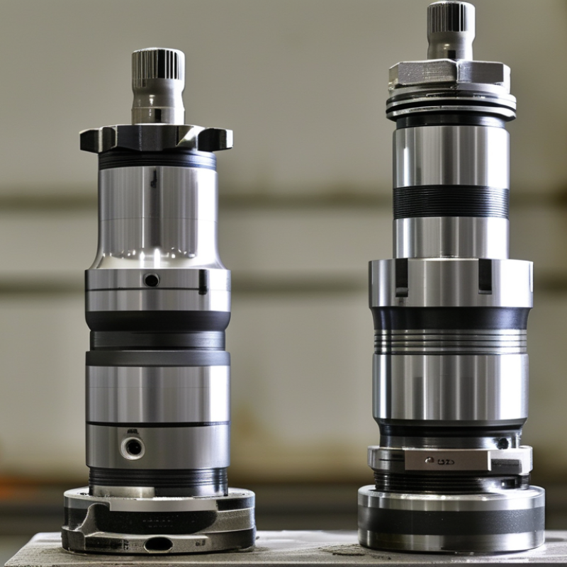
A CNC coupling connects the motor shaft to the machine’s driven shaft. It transfers torque while allowing limited movement between both shafts. This movement may include angular, parallel, or axial misalignment. The coupling also helps reduce vibration during rapid acceleration and deceleration.
In a CNC milling machine, the coupling directly affects positioning accuracy. During commissioning, I check shaft alignment, screw tightness, and visible wear. Small errors matter. A typical coupling contains two hubs, a flexible element, and fastening hardware. The hubs grip the shafts, while the flexible section absorbs minor alignment errors. Metallic designs offer high torsional stiffness, while elastomeric elements often provide better vibration damping. Each structure creates a different balance between precision, flexibility, and service life. A coupling can look perfect but still perform poorly.
When the motor rotates, torque passes through the hubs and flexible section. The element bends or twists slightly as the shafts move. This controlled deformation protects bearings, screws, and motors from sudden loads. However, excessive misalignment creates heat, noise, and fatigue. Before choosing a coupling, measure shaft diameters, required torque, speed, and available installation space. Check the machine’s temperature and duty cycle too. I have seen couplings selected only by torque rating, which was a costly mistake. Perfect alignment is not always practical, but careless alignment is rarely acceptable.
A CNC coupling transmits torque between a motor and a driven shaft while accommodating small alignment errors. The chart shows representative midpoint values for typical angular misalignment capacity by coupling construction. Higher flexibility can improve alignment tolerance, while bellows and disc couplings are generally preferred when high torsional stiffness and accurate motion transfer are required.
Selection guidance: Choose the coupling according to torque, speed, torsional stiffness, allowable misalignment, backlash, installation space, and environmental conditions. Always confirm the final value against the selected coupling’s engineering datasheet.
Identify the motion and load requirements before comparing coupling materials or prices. A CNC axis may combine high speed, frequent reversals, vibration, and thermal growth. Record peak torque, continuous torque, acceleration, speed, and duty cycle from machine data. Measure radial, angular, and axial misalignment at the actual shaft positions. Do not rely only on catalog limits. A coupling rated for nominal torque may fail under repeated acceleration.
The International Federation of Robotics reported 541,302 industrial robot installations worldwide in 2023 in its World Robotics 2024 report. This growth reflects more demanding automated motion systems. It also highlights a practical issue: higher cycle rates expose backlash, poor balance, and insufficient torsional stiffness quickly. Choose a coupling with a service factor suited to reversing loads. Check the bore, keyway, clamping method, allowable speed, and shaft stiffness together.
Measure it cold.
Thermal expansion can shift alignment after hours of cutting. A helical coupling may suit moderate misalignment, while a disc coupling can provide higher torsional stiffness. Flexible designs are not automatically safer. Excess flexibility can reduce positioning accuracy during rapid direction changes. I have seen selection sheets ignore emergency-stop loads and tool-change impacts. That is an avoidable weakness.
Review the result against ISO 12100 risk principles and the coupling manufacturer’s verified test data. The U.S. Department of Energy’s Industrial Decarbonization Roadmap also emphasizes efficiency losses from industrial motion systems, reminding engineers that alignment and transmission losses affect more than maintenance. Test the selected coupling under real acceleration profiles, not only steady rotation.
Choosing a CNC coupling requires more than matching shaft diameter. In machining trials, small backlash can leave visible tool marks on aluminum parts. Beam couplings offer flexibility and simple installation, but their torsional stiffness may limit heavy cutting. Bellows couplings provide excellent precision and low backlash. They suit servo axes demanding accurate positioning. Disc couplings handle higher torque and speed, although alignment becomes more demanding. Even a slight angular error can increase bearing loads.
Speed changes the decision. At high RPM, an unbalanced coupling may create vibration across the spindle housing. A compact jaw coupling can absorb shock and tolerate modest misalignment. Its flexible insert also reduces transmitted noise.
However, that insert wears. Check it regularly. For machines with frequent acceleration, select a coupling with suitable torsional stiffness, not only a high maximum RPM.
Flexibility also includes maintenance and installation time. Measure shaft runout, axial movement, and operating temperature before choosing. Ask whether technicians can replace the element without moving the motor. I once underestimated thermal growth during long production cycles. The coupling survived, but positioning drift appeared after several hours. That mistake changed the selection process. Review the actual duty cycle, cutting load, and alignment method. A coupling that performs well in a catalog test may behave differently beside coolant, chips, and repeated starts.
Choosing a CNC coupling starts with material, not price. Steel couplings suit high torque and harsh machining environments. Aluminum reduces rotating mass and servo load. Stainless steel helps resist coolant and humidity. In practice, I once selected a lightweight coupling for speed, but ignored thermal growth. The machine later showed unstable positioning. That mistake was avoidable.
Accuracy depends on more than rated backlash. Check bore tolerance, concentricity, torsional stiffness, and balance quality. ISO 230-2 defines methods for evaluating machine-tool positioning accuracy and repeatability. ISO 1940-1 also links balancing quality with rotating-component performance. These standards do not choose the coupling for you. They create a disciplined measurement basis. Allowable angular and parallel misalignment must match the actual shaft geometry. A coupling that tolerates too much movement may still reduce servo response. Small numbers matter.
Tips: Measure both shafts after warm-up. Record vibration, temperature, and backlash. The U.S. Department of Energy’s compressed-air performance sourcebook reports that leaks can waste 20–30% of compressor output. Coolant, dust, and nearby pneumatic leaks can influence service conditions, even when the coupling is enclosed. Select seals and finishes accordingly. Recheck alignment during maintenance. A datasheet rarely captures the whole machine. That is the uncomfortable part. Calculation can still miss real operating behavior.
| Coupling Type | Typical Construction Materials | Typical Torque Range | Angular Misalignment | Parallel Misalignment | Axial Motion | Typical Backlash | Positioning Accuracy and Stiffness | Service Temperature | Best CNC Applications |
|---|---|---|---|---|---|---|---|---|---|
| Bellows Coupling | Stainless-steel or nickel-alloy bellows with aluminum or steel hubs. | Approximately 5–2,000 N·m | Typically 1°–2° | Typically 0.1–0.5 mm | Typically 0.2–1.0 mm, depending on bellows design | Zero backlash when properly clamped | Very high torsional stiffness and excellent repeatability | Commonly about −40°C to +120°C; verify the actual bellows and hub limits | Servo-driven CNC axes, rotary tables, precision stages, and applications requiring accurate bidirectional positioning. |
| Disc Coupling | Stainless-steel disc packs with aluminum or steel hubs and spacer assemblies. | Approximately 10–10,000 N·m | Typically 0.5°–1.5° | Typically 0.2–1.0 mm | Limited axial compensation; commonly 0.5–2.0 mm | Zero backlash when correctly assembled | High torsional stiffness, good fatigue resistance, and reliable synchronization | Commonly about −30°C to +120°C | High-speed spindles, servo axes, rotary axes, and systems exposed to cyclic torque or moderate shock loads. |
| Elastomeric Jaw Coupling | Aluminum, steel, or stainless-steel hubs with polyurethane or similar elastomer spiders. | Approximately 1–2,500 N·m | Typically 1°–1.5° | Typically 0.2–0.8 mm | Typically 0.5–1.5 mm | Low to moderate; depends on spider hardness and wear | Moderate stiffness; excellent vibration and shock damping | Commonly about −30°C to +80°C; elastomer grade is critical | General CNC feed drives, pumps, auxiliary axes, applications with moderate alignment error or motor vibration. |
| Oldham Coupling | Aluminum or steel hubs with an acetal, nylon, or other engineering-polymer center disc. | Approximately 0.5–250 N·m | Typically 1°–2° | Typically 0.5–1.5 mm | Limited; design-dependent | Low backlash when new; center-disc wear can increase backlash | Good radial flexibility with moderate torsional stiffness | Commonly about −20°C to +80°C; polymer limits must be checked | Compact servo mechanisms, encoder drives, light-duty CNC axes, and installations with noticeable parallel offset. |
| Beam or Helical Coupling | Machined aluminum or stainless-steel spring-metal body, usually produced from one piece. | Approximately 0.1–100 N·m | Typically 1°–5°, depending on beam geometry | Typically 0.1–0.5 mm | Typically 0.2–1.0 mm | Zero backlash when undamaged | Good precision at low torque; torsional stiffness is lower than bellows or disc designs | Commonly about −30°C to +100°C | Low-torque positioning stages, encoders, inspection equipment, and compact CNC mechanisms. |
| Rigid Sleeve Coupling | Steel, stainless steel, or aluminum sleeve with clamping or keyed hub connections. | Approximately 10–20,000 N·m | Effectively 0° by design | Effectively 0 mm by design | No intentional compensation | Zero backlash when correctly fitted | Very high torsional stiffness, but it transfers shaft misalignment directly to bearings | Usually about −40°C to +150°C, subject to material and lubrication limits | Precisely aligned shafts, rigid transmission assemblies, and test fixtures where alignment can be controlled tightly. |
| Gear Coupling | Hardened steel hubs and sleeves with tooth flanks; normally requires suitable lubricant. | Approximately 100–100,000 N·m | Typically 0.5°–1.5° | Typically 0.5–3.0 mm, depending on size | Often available through sliding tooth engagement | Low backlash versions are available; standard designs may have measurable backlash | High torque capacity and stiffness, but usually less suitable for precision positioning than bellows or disc types | Commonly about −20°C to +100°C with correct lubricant selection | High-torque rotary equipment, large machine axes, and drives where load capacity is more important than ultra-low backlash. |
| Magnetic Coupling | Permanent magnets enclosed by stainless steel, aluminum, or engineering-polymer barriers. | Approximately 0.1–500 N·m | Design-dependent; usually not intended to compensate for large alignment errors | Design-dependent; alignment should generally be controlled accurately | Design-dependent | No mechanical tooth backlash; torque slip can occur under overload | Useful for sealed transmission, but torsional stiffness and synchronization depend on magnetic design | Often about −20°C to +100°C; magnet and barrier materials must be verified | Sealed or contamination-sensitive mechanisms where a physical shaft seal is undesirable. |
| Selection note: The published ranges are representative engineering ranges rather than universal ratings. Final selection should be based on transmitted torque, peak and reversing loads, maximum speed, shaft diameter, bore fit, allowable misalignment, torsional stiffness, ambient temperature, contamination, maintenance access, and the coupling manufacturer's verified rating for the complete assembly. | |||||||||
Choosing the right CNC coupling starts with the machine’s real motion profile, not only shaft diameter.
Measure bore sizes, shaft spacing, torque, speed, and allowable misalignment before ordering. For a milling spindle, prioritize low runout and balanced construction. For a feed axis, torsional stiffness and backlash matter more. Check acceleration peaks, not just average torque. A coupling rated exactly at the calculated load may be too close for aggressive cycles. Leave a practical service margin, but avoid excessive sizing, which can increase inertia.
Installation rewards patience. Clean both shafts with a lint-free cloth, then inspect keyways, shoulders, and clamping surfaces. A small burr can prevent full seating and create vibration that looks like a bearing fault.
Align the shafts with a dial indicator or suitable laser tool, while respecting the coupling’s specified limits. Do not force a flexible element to correct poor machine alignment. Tighten fasteners in a cross pattern and use the documented torque value. I have seen technicians skip this step, then chase repeatability problems for hours.
Maintenance should follow operating hours and machine behavior.
During inspections, check clamp movement, cracks, dust buildup, unusual heat, and fretting marks. Record vibration, temperature, and backlash trends instead of relying on memory. Replace worn components before metal contact damages the shafts.
Lubrication is not automatically helpful; many couplings require no lubricant, and contamination can shorten service life. Recheck alignment after a crash, motor replacement, or repeated thermal changes. My early mistake was treating installation as a one-time task. It is not.