- sales@bjbod.com
- Mon - Sat at 7:00AM to 9:00PM
Inquiry
Form loading...
Choosing the right Cnc Drawbar can change how a machine feels during everyday production. This compact mechanism pulls the toolholder firmly into the spindle taper. That pressure supports stable cutting, reliable tool seating, and faster tool changes. In a busy workshop, the difference appears in small details. Operators spend less time tightening tools by hand. Setup becomes more consistent. Downtime can also become easier to predict.
Performance depends on more than speed. A suitable Cnc Drawbar must match the spindle taper, pull stud, clamping force, and machine design. Incorrect specifications may cause toolholder movement, poor surface finishes, or accelerated spindle wear. Manufacturer data should guide the selection. Maintenance records matter, too. Inspecting springs, grippers, threads, and contact surfaces can reveal problems before they interrupt production. Clean contact surfaces are essential.
Small component. Serious responsibility.
A well-designed power drawbar may improve ergonomics and support repeatable work across long shifts. It can also help operators maintain consistent clamping pressure between tool changes. However, automation does not remove the need for judgment. Some systems require careful adjustment, and older machines may need additional checks. It is tempting to treat every drawbar as a simple upgrade. That assumption can be wrong. Real results depend on installation quality, spindle condition, tooling accuracy, and disciplined inspection. A practical evaluation should compare cycle time, clamping reliability, service access, and long-term operating cost. This approach supports safer decisions and more dependable machining performance.
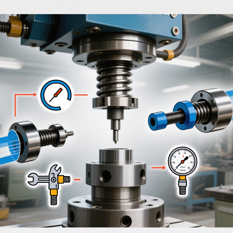
A CNC drawbar is the spindle’s internal clamping device. It secures a toolholder inside the spindle taper during cutting. Most systems use strong disc springs to create constant pulling force. A pull stud connects the toolholder to the drawbar. When compressed air activates the release cylinder, the drawbar moves upward. The toolholder then becomes free for manual or automatic removal.
It holds firmly. During machining, the taper transfers cutting forces and helps maintain tool alignment. This design supports repeatable tool changes and reduces setup time. It also protects operators from handling loose holders near a moving spindle. In practical use, the correct pull force matters greatly. Excessive force can stress the spindle and toolholder. Insufficient force may allow vibration, poor surface finish, or tool movement.
A reliable drawbar needs clean contact surfaces, correct spring tension, and regular inspection. Chips inside the taper can create tiny alignment errors. Those errors may appear as uneven wear or unexpected runout. Technicians should check the pull stud, springs, lubrication points, and release pressure. Small details matter. I have found that maintenance schedules are often too optimistic. Actual production dust, coolant, and frequent tool changes can shorten service intervals. A drawbar is simple in principle, but its performance depends on careful adjustment and honest observation.
| Data Dimension | Typical Data or Description | Why It Matters |
|---|---|---|
| Basic definition | A CNC drawbar is a machine-tool clamping mechanism that pulls a toolholder into the spindle taper. | It creates a rigid connection between the spindle and the cutting tool during machining. |
| Main operating principle | Disc springs or other spring elements generate the normal clamping force; an actuator releases the force for tool changes. | The tool remains clamped if actuation pressure is lost, provided the mechanism is correctly adjusted. |
| Common actuation methods | Pneumatic release is widely used on automatic tool-change machines; hydraulic and manual systems are also available. | The actuation method affects tool-change speed, installation requirements, and maintenance needs. |
| Typical clamping-force range | Approximately 4–25 kN for many small- to medium-size CNC spindle systems; larger tapers may require higher forces. | Adequate force helps resist toolholder pull-out, vibration, and movement under cutting loads. |
| Toolholder compatibility | The drawbar must match the spindle taper, toolholder retention system, pull-stud geometry, thread, and required clamping force. | Incorrect matching can cause poor retention, taper damage, runout, or unsafe tool release. |
| Typical construction materials | Heat-treated alloy steel is commonly used for the drawbar, while springs and retaining components are selected for repeated cyclic loading. | Material strength and heat treatment influence fatigue life, wear resistance, and dimensional stability. |
| Tool-change performance | Automatic systems can release a tool in a few seconds, depending on the machine, actuator, control sequence, and tool changer. | Faster and repeatable tool changes reduce non-cutting time in production. |
| Runout and rigidity | A correctly adjusted drawbar supports a rigid taper interface; actual runout depends on the spindle, toolholder, taper cleanliness, and tool assembly. | Stable clamping improves dimensional accuracy, surface finish, and tool life. |
| Key maintenance items | Check clamping force, spring condition, pull-stud wear, lubrication, taper cleanliness, and release-stroke adjustment. | Routine inspection helps prevent tool slippage, inconsistent machining, and unexpected downtime. |
| Main advantages | High retention force, repeatable positioning, compatibility with automatic tool changes, and improved spindle-tool rigidity. | These benefits support higher productivity and more consistent CNC machining results. |
| Selection checklist | Verify spindle model, taper standard, drawbar length, thread and pull-stud specification, release pressure, clamping force, and available installation space. | Accurate selection ensures safe operation and prevents compatibility problems during installation. |
Note: Specifications are typical engineering ranges and must be confirmed against the machine builder’s spindle and toolholder requirements before replacement or installation.